custom projection
A custom 3D to 2D projection to render the 3D geometry as 2D shapes for the underlying 2D engine.
A research project exploring how far I could go building a
DOOM-like rendering pipeline from scratch.
Instead of using a 3D engine, I worked within a limited 2D engine. From there I built my own
projection system and used the original DOOM level data as
the source for the world.
What started as an experiment with projecting 3D geometry onto
a 2D screen eventually grew into a study of WAD file structures,
geometry construction, BSP trees, depth sorting and collision.
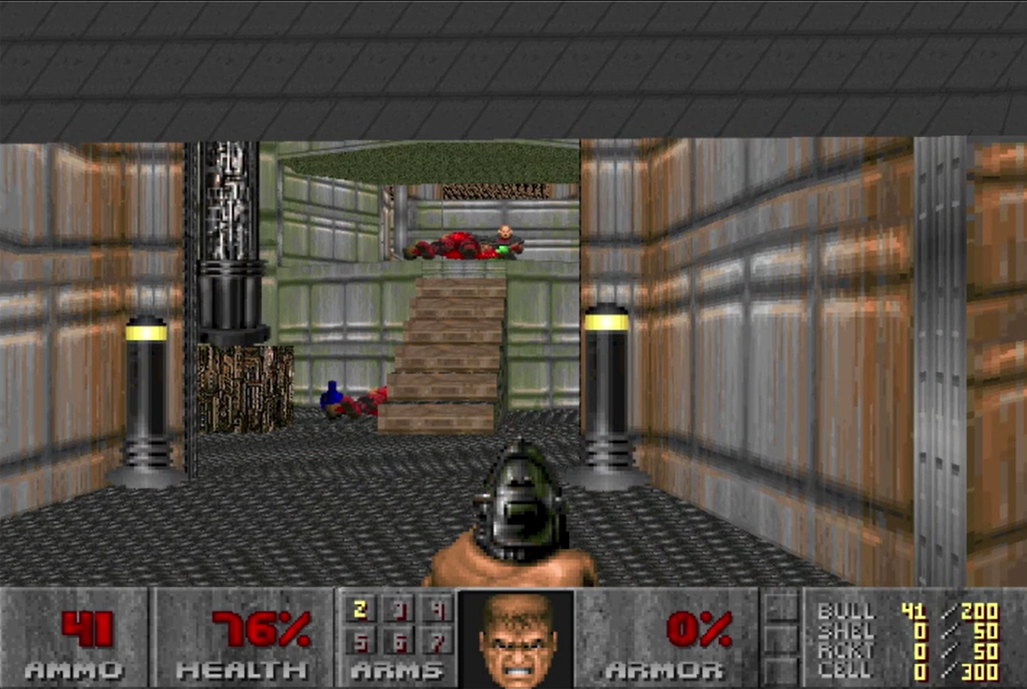
DOOM - reconstructed
The goal of the project was not to recreate the entire DOOM game. It was instead to create a system
capable of loading and building the original DOOM level data and make it available to be rendered
and explored like in the original game.
A custom 3D to 2D projection to render the 3D geometry as 2D shapes for the underlying 2D engine.
A system for loading the original DOOM level files, capable of utilizing and resolving the information in the different data structures
Reconstruction of walls, floors and ceilings from the vertices, linedefs, sidedefs and sector data contained in the level.
Using BSP-trees ( my saving grace ) for level construction, spatial ordering, depth sorting and collision testing.
Implementing the elements used to create the game experience such as enemy behaviour, weapon usage and pickups.
This resulted in the following workflow:
Level Loading
↓
DOOM WAD files
The original files containing the raw condensed level information.
↓
WAD parser
Extracts the relevant data, and works out the relationships for construction.
↓
Geometry construction 1 - BSP
Using the BSP, floors and ceilings are constructed, attaching the relation to their relative
sector and place in the BSP for real time reference.
↓
geometry construction 2
From lines, sidedefs, vertices and sectors, all the walls are constructed and assigned to the
relative sectors.
↓↓
Real Time
↓
3D -> 2D projection
The 3D vertex positions are translated to 2D screen space, utilizing the BSP for draw order.
↓
2D rendering
This is the question that started the whole project:
Could I project 3D space on a 2D screen without relying on established techniques?
It was something that had fascinated me already during my art education.
And, while refreshing my math for my c++ education, I got intrigued by radians, and the
relationship between angles and positions around a camera.
This relationship became the basis of my projection system.
A point's angle, relative to the camera's forward direction determines its horizontal position on screen
A similar technique can be used to derive the vertical position, achieving full natural perspective.
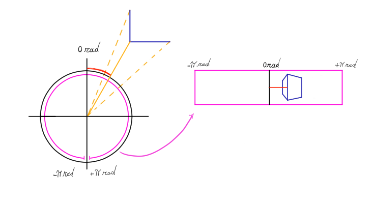
Like this, 3D planes could be converted into 2D trapezoids that the existing 2D engine could draw.
The basic projection was relatively straightforward.
The difficult part was making it robust,
especially for larger planes where edge cases became more glaring:
geometry-camera intersections, finding part of a plane to be behind,
and part of a plane in front of the camera, etc.
These cases produced jumps or unnatural scaling. therefore, each point had it's natural screen position, as well as it's corrected position, which clips the geometry behind the camera, and recalculates for the intersection point instead.
all while keeping the calculations manageable. After all, as I didnt have access to the gpu,
the entire level projection had to be calculated on the CPU every frame.
In essence this became:
world position
↓
subtracting camera position to go to Camera-Location/World-Rotation space
↓
using x and y to find the object angle
↓
subtracting camera rotation to go to full camera space
↓
use angle to determine raw screen space location
↓
edge case handeling, clipping the position and using previous position to prevent big jumps between extremes (-PI & PI)
↓
determine final visibility and location on screen
Because not all geometry intersections happen at a shared vertex, and the way the projection system works, some of these intersections become visualy inconsistent as the camera moves through the world.
This could be mitigated in the project by ensuring all intersections happen at a vertex rather than at the edge of one shape and the vertex of another.
A traditional rasterization pipeline would also take care of this issue. That became a separate project of its own. :)
Explore the rasterizer! ->
Once the projection system was working, I wanted to move beyond manually inputting geometry.
Since the goal was to recreate a DOOM level, I wanted to use the original game data rather than a recreation model or my own estimation.
This introduced a completely different problem:
How do I turn a collection of interconnected, tightly packed, binary data
structures into geometry my renderer understands?
DOOM's level data contains a lot of information and it is divided into multiple structures. Each describes not just a different part of the map, but a different facet of the geometry which is interconected with the other data.
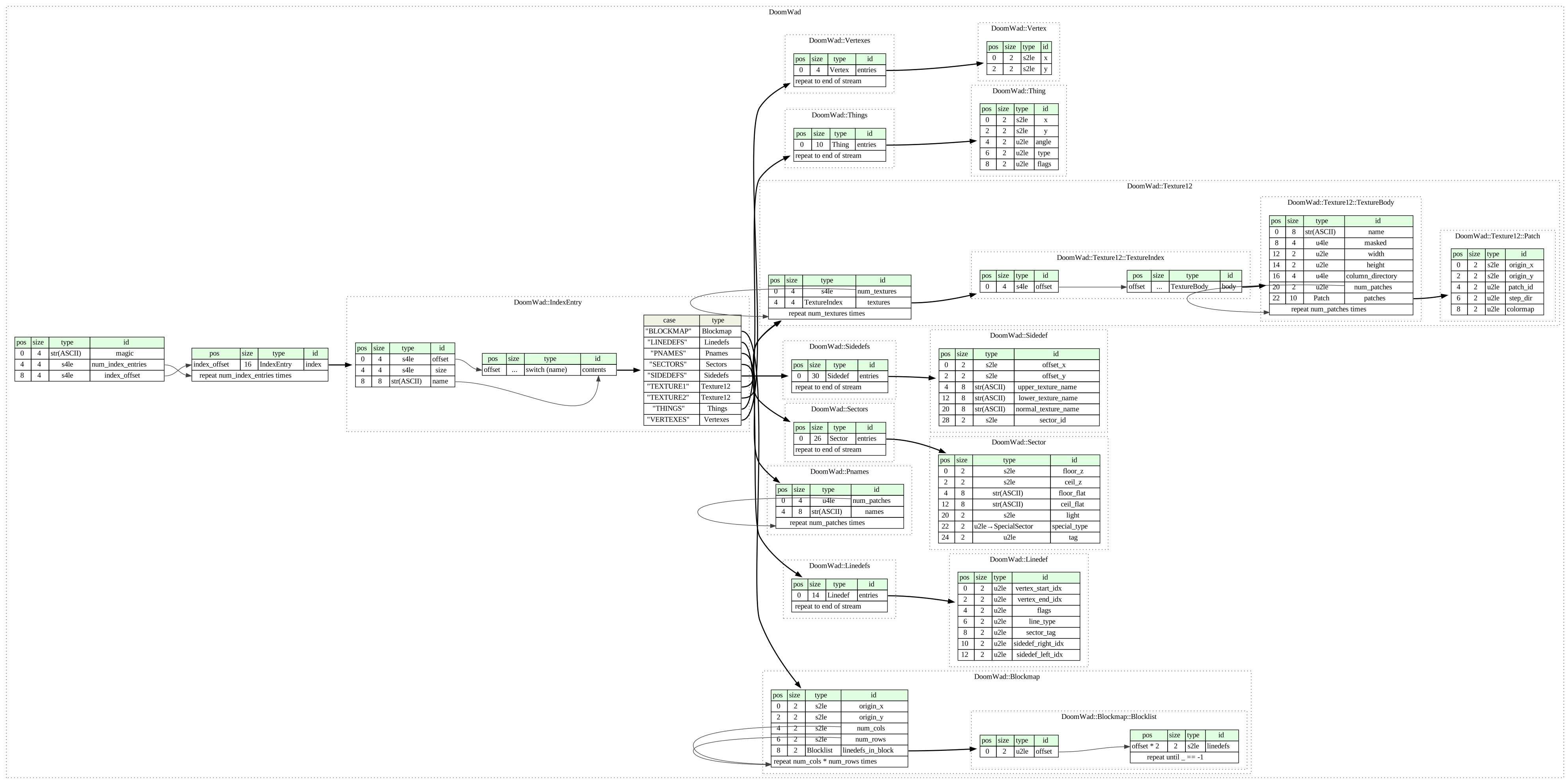
The most important structures for reconstructing the level geometry were:
VERTEXES: Each point defining the map's surface area.
LINEDEFS: Lines connecting vertices and referencing their associated sidedef(s).
SIDEDEFS: Information describing the sides of walls, including textures, texture offsets and sector references.
SEGS : Sections of wall that belong to a single convex subsector.
SSECTORS: Range of segs needed to create a single convex area, references in the BSP leaf nodes.
SECTORS : Information about floor and ceiling heights, textures and other properties of the level's spaces.
NODES : The BSP tree describing how the level is spatially partitioned.
So the chalenge was not simply reading the files. It was following the interconnected references between them and transforming that information into comprehensible geometry.
I eventually built a pipeline capable of extracting the information required to reconstruct the level geometry at runtime.
As the level loading remained a work in progress throughout most of the project,
the pipeline currently does not make full use of the line segments generated by the BSP tree.
These segments divide walls at important intersections and would most likely resolve
the remaing sorting issues as well as the earlier mentioned visual inconsistencies.
Extracting the verticies was easy enough, but sadly only the beginning.
At first, the verticies were essentialy point clouds, by linking a few pieces of information together I could discern what sector they belonged to. But no more than that. This send me to polygon generation and triangulation, which brought me many ungodly shapes.
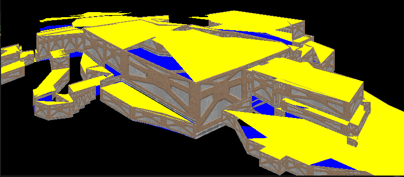
yellow:roofs | blue:floors | texture:walls
Extracing the vertex order was not a straightforward task
(I'd later realise why).
There was no vertex trail to follow. I did have the wall definitions and segments though...
But, these things were not cleanly linked to the walls that suround a room. Especialy for the larger areas with a lot of neighbors.
So, to extract the order, I had to build an algorithm that could follow
a wall trail, cross reference it with the segment trails
and both break and infer vertex conections where needed.
This kept track of flipped wall directions(vtx1->vtx2 vs vtx2->vtx1), shared walls, implied loops, and how often a vertex was used to discern individual areas.
Once each room had an ordered array of verticies,
I could fall back on established mathematical
triangulation techniques to create both convex and concave polygons.
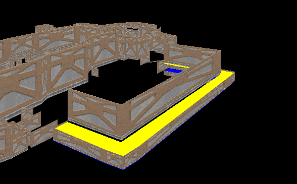
Whilst this worked, it exposed a glaring issue: visibility.
Large concave surfaces can overlap with each other so that the same surface may be both in front and behind something else.
Meaning that while I now had the geometry, I had no way to consistently decide the draw order.
In the end, the floors and ceilings get constructed in acordance with the convex subsectors, for which the vertex order came naturaly.
This makes a large part of this research redundant, but it was still a great learning experience and an important step in the process to expose underlying issues.
The breakthrough came from understanding the BSP tree that is already stored in the DOOM level data.
Binary Space Partitioning
A Binary Space Partition tree
recursively divides a space using a partition line which gets stored.
This allows the space to consistently be traversed in order, no matter the starting position in the tree.
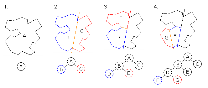
For DOOM specificaly, the leaf nodes of this BSP tree are the subsectors. These subsectors describe
the largest posible areas in which line of sight is guaranteed.
By concequence, all of them are convex.
Rather than crossreferencing the data to find the vertex order, I could now instead start with a rectangle that encompasses the entire level, after which I can use the partition lines to recursively slice the surface untill a single subsector is produced.
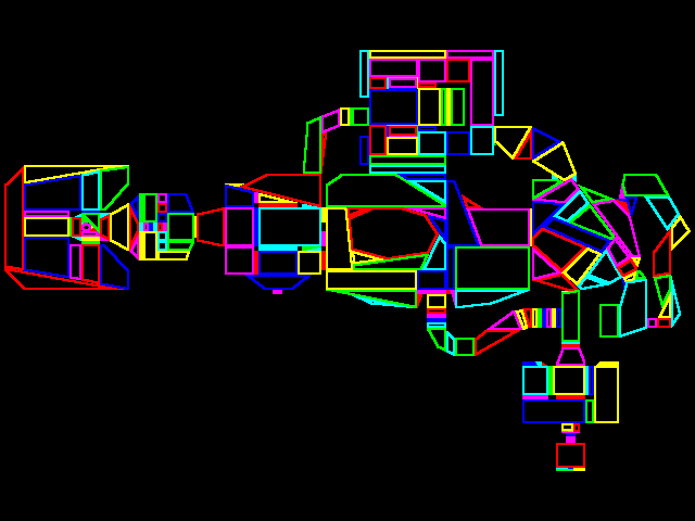
This solved 2 issues basically for free:
By traversing the BSP tree from the camera's position, all the geometry can be sorted spatially without needing to do line of sight or distance checks.
The BSP's relation to the subsectors also reduces the amount of geometry that needs to be considered for collision testing. Rather than the entire level, I can simpley test against the handfull of walls present in the current subsector.
The BSP also divides walls into separate segments.
The current level reconstruction does not yet
make full use of these splits.
Incorporating the generated segments would address
some remaining sorting issues.
With the rendering and level pipeline working, there was still gameplay systems.
- automatic doors
- enemies that walk and attack with line of sight
- shooting and killing enemies
- picking up weapons, ammo, armour, healing, boosts
- UI
The positioning and types of these are equaly taken
from the original level data.
Once in place, this turned
the reconstructed levels into a playable experience.
gameplay - DOOM reconstructed
The result is a robust system capable of reconstructing original DOOM levels for a small 2D engine, projecting them and making them (minimally) playable.
This project taught me a lot, its scope growing together with my programming skills and sparking my interest and insight in a varied set of subjects. It also taught me that separate issues don't always need separate solutions, and that reading documentation, doing research, and experimenting are the difference between ~working~ code and robust code.